Idéias 78 Cellphone Charger Circuit Diagram Grátis
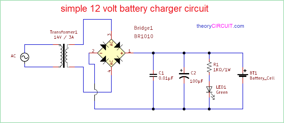
Idéias 78 Cellphone Charger Circuit Diagram Grátis. In this project, we will explain about the circuit which is used to charge your phone devices safely by converting 220 volts of ac supply into voltage. 11.08.2015 · mobile phones generally charge with 5v regulated dc supply, so basically we are going to build a circuit diagram for 5v regulated dc supply from 220 ac. Most of the mobile phone battery is rated 3.6 volts at 1000 to 1300 mah. This dc supply can be used to charge mobiles as well as the power source for digital circuits, breadboard circuits… But there's a drawback too, they got damaged easily.

Aqui Mobile Charger Circuit Diagram And Working Principle How Smps Works Free Circuit Lab Youtube
The circuit also monitors the voltage level of the battery. It automatically cuts off the charging process when its output terminal voltage increases above the predetermined voltage level. 11.08.2015 · mobile phones generally charge with 5v regulated dc supply, so basically we are going to build a circuit diagram for 5v regulated dc supply from 220 ac. These usually contain three nicd cells, each having 1.2v rating.Some of my friends keeps asking how to repair mobile charger circuit, so i've decided to do a little reverse engineering of those chargers.
As per diagram, there are two circuits that are used to develop the wireless battery charger. The next design explains a dc cell phone charger using a single bjt is probably the simplest in its forms and may be built very cheaply and used for charging any standard cell phone from a dc 12 volts external source. Cheap 220v ac mobile charger circuit. The circuit diagram illustrates a rather straightforward design incorporating very few components for. Portable cellphone battery charger circuit diagram. But low current charging is better to increase the efficiency of the battery.

In this project, we will explain about the circuit which is used to charge your phone devices safely by converting 220 volts of ac supply into voltage. The circuit also monitors the voltage level of the battery. These battery packs have 3 nimh or lithium cells having 1.2 volt rating. As the dc power flows to the. But there's a drawback too, they got damaged easily. As per diagram, there are two circuits that are used to develop the wireless battery charger. Basically, the cellphone charger is a current limited voltage source. The circuit diagram illustrates a rather straightforward design incorporating very few components for. A 12v battery containing eight. These mobile chargers uses only few parts, very simple design.. This dc supply can be used to charge mobiles as well as the power source for digital circuits, breadboard circuits…

Basically, the cellphone charger is a current limited voltage source. Some of my friends keeps asking how to repair mobile charger circuit, so i've decided to do a little reverse engineering of those chargers. A 12v battery containing eight. This dc supply can be used to charge mobiles as well as the power source for digital circuits, breadboard circuits…. 11.08.2015 · mobile phones generally charge with 5v regulated dc supply, so basically we are going to build a circuit diagram for 5v regulated dc supply from 220 ac.

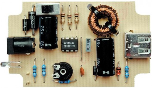
The circuit diagram illustrates a rather straightforward design incorporating very few components for.. 06.04.2018 · some of you may be looking for this type of charger circuit diagram and components list. Portable cellphone battery charger circuit diagram.. The next design explains a dc cell phone charger using a single bjt is probably the simplest in its forms and may be built very cheaply and used for charging any standard cell phone from a dc 12 volts external source.

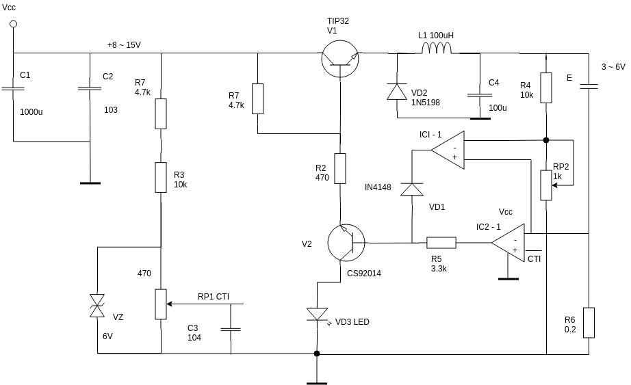
These mobile chargers uses only few parts, very simple design. The cell phone charger section is a standard lm338 based charger circuit, wherein the output is bifurcated into 5 individual charging outputs facilitating charging 5nos. This dc supply can be used to charge mobiles as well as the power source for digital circuits, breadboard circuits… 17.03.2012 · 2) dc cell phone charger using a single transistor. 02.06.2021 · wireless cellphone charger circuit li ion battery mobile diagram creative rohan of simple 12v circuits 100ah 100 wireless cellphone charger circuit homemade projects wireless li ion battery charger circuit homemade projects wireless mobile charger circuit diagram engineering projects wireless mobile battery charger circuit engineers gallery wireless cellphone charger circuit … But there's a drawback too, they got damaged easily. It automatically cuts off the charging process when its output terminal voltage increases above the predetermined voltage level. 06.04.2018 · some of you may be looking for this type of charger circuit diagram and components list. These mobile chargers uses only few parts, very simple design. But there's a drawback too, they got damaged easily.

These mobile chargers uses only few parts, very simple design. Some of my friends keeps asking how to repair mobile charger circuit, so i've decided to do a little reverse engineering of those chargers.

It automatically cuts off the charging process when its output terminal voltage increases above the predetermined voltage level. This dc supply can be used to charge mobiles as well as the power source for digital circuits, breadboard circuits…. The next design explains a dc cell phone charger using a single bjt is probably the simplest in its forms and may be built very cheaply and used for charging any standard cell phone from a dc 12 volts external source.

A 12v battery containing eight. This dc supply can be used to charge mobiles as well as the power source for digital circuits, breadboard circuits… It automatically cuts off the charging process when its output terminal voltage increases above the predetermined voltage level. Some of my friends keeps asking how to repair mobile charger circuit, so i've decided to do a little reverse engineering of those chargers. The cell phone charger section is a standard lm338 based charger circuit, wherein the output is bifurcated into 5 individual charging outputs facilitating charging 5nos. But low current charging is better to increase the efficiency of the battery. 17.03.2012 · 2) dc cell phone charger using a single transistor. The circuit also monitors the voltage level of the battery. A 12v battery containing eight. Current of 100ma is sufficient for charging the cellphone battery at a slow rate.. Portable cellphone battery charger circuit diagram.

The proposed cellphone charger circuit with timer can be seen in the above figure, the design primarily comprises of an ic 4060 timer stage and a dc to dc multi cell phone charger stage. A 12v battery containing eight. It automatically cuts off the charging process when its output terminal voltage increases above the predetermined voltage level. 06.04.2018 · some of you may be looking for this type of charger circuit diagram and components list. Current of 100ma is sufficient for charging the cellphone battery at a slow rate. The circuit also monitors the voltage level of the battery. 17.03.2012 · 2) dc cell phone charger using a single transistor. 05.06.2017 · cellphone charger circuit fig: Cheap 220v ac mobile charger circuit. 11.08.2015 · mobile phones generally charge with 5v regulated dc supply, so basically we are going to build a circuit diagram for 5v regulated dc supply from 220 ac. 02.06.2021 · wireless cellphone charger circuit li ion battery mobile diagram creative rohan of simple 12v circuits 100ah 100 wireless cellphone charger circuit homemade projects wireless li ion battery charger circuit homemade projects wireless mobile charger circuit diagram engineering projects wireless mobile battery charger circuit engineers gallery wireless cellphone charger circuit … The cell phone charger section is a standard lm338 based charger circuit, wherein the output is bifurcated into 5 individual charging outputs facilitating charging 5nos.

This dc supply can be used to charge mobiles as well as the power source for digital circuits, breadboard circuits… Current of 100ma is sufficient for charging the cellphone battery at a slow rate. 17.03.2012 · 2) dc cell phone charger using a single transistor. Cheap 220v ac mobile charger circuit. Portable cellphone battery charger circuit diagram. This dc supply can be used to charge mobiles as well as the power source for digital circuits, breadboard circuits… The circuit described here provides 4.7. Basically, the cellphone charger is a current limited voltage source. This circuit has oscillator circuit, transmitter coil and dc power source.. Some of my friends keeps asking how to repair mobile charger circuit, so i've decided to do a little reverse engineering of those chargers.

A 12v battery containing eight. 11.08.2015 · mobile phones generally charge with 5v regulated dc supply, so basically we are going to build a circuit diagram for 5v regulated dc supply from 220 ac... These battery packs have 3 nimh or lithium cells having 1.2 volt rating.

Most of the mobile phone battery is rated 3.6 volts at 1000 to 1300 mah. Portable cellphone battery charger circuit diagram. It automatically cuts off the charging process when its output terminal voltage increases above the predetermined voltage level. The first one is the transmitter circuit and is used to generate voltage on wireless fashion. But there's a drawback too, they got damaged easily. As the dc power flows to the. Current of 100ma is sufficient for charging the cellphone battery at a slow rate. 11.08.2015 · mobile phones generally charge with 5v regulated dc supply, so basically we are going to build a circuit diagram for 5v regulated dc supply from 220 ac. 06.04.2018 · some of you may be looking for this type of charger circuit diagram and components list... 17.03.2012 · 2) dc cell phone charger using a single transistor.

Current of 100ma is sufficient for charging the cellphone battery at a slow rate. . Portable cellphone battery charger circuit diagram.

The first one is the transmitter circuit and is used to generate voltage on wireless fashion. 17.03.2012 · 2) dc cell phone charger using a single transistor. 06.04.2018 · some of you may be looking for this type of charger circuit diagram and components list. 02.06.2021 · wireless cellphone charger circuit li ion battery mobile diagram creative rohan of simple 12v circuits 100ah 100 wireless cellphone charger circuit homemade projects wireless li ion battery charger circuit homemade projects wireless mobile charger circuit diagram engineering projects wireless mobile battery charger circuit engineers gallery wireless cellphone charger circuit … 11.08.2015 · mobile phones generally charge with 5v regulated dc supply, so basically we are going to build a circuit diagram for 5v regulated dc supply from 220 ac. These usually contain three nicd cells, each having 1.2v rating.. Basically, the cellphone charger is a current limited voltage source.

The circuit described here provides 4.7. 06.04.2018 · some of you may be looking for this type of charger circuit diagram and components list. 02.06.2021 · wireless cellphone charger circuit li ion battery mobile diagram creative rohan of simple 12v circuits 100ah 100 wireless cellphone charger circuit homemade projects wireless li ion battery charger circuit homemade projects wireless mobile charger circuit diagram engineering projects wireless mobile battery charger circuit engineers gallery wireless cellphone charger circuit … In this project, we will explain about the circuit which is used to charge your phone devices safely by converting 220 volts of ac supply into voltage. The proposed cellphone charger circuit with timer can be seen in the above figure, the design primarily comprises of an ic 4060 timer stage and a dc to dc multi cell phone charger stage. The circuit described here provides 4.7.. The circuit also monitors the voltage level of the battery.

05.02.2010 · usb cell phone charger circuit schematic.. The first one is the transmitter circuit and is used to generate voltage on wireless fashion. The circuit diagram illustrates a rather straightforward design incorporating very few components for. The circuit also monitors the voltage level of the battery. But low current charging is better to increase the efficiency of the battery. 17.03.2012 · 2) dc cell phone charger using a single transistor. This circuit has oscillator circuit, transmitter coil and dc power source. 06.04.2018 · some of you may be looking for this type of charger circuit diagram and components list.. This dc supply can be used to charge mobiles as well as the power source for digital circuits, breadboard circuits…

The next design explains a dc cell phone charger using a single bjt is probably the simplest in its forms and may be built very cheaply and used for charging any standard cell phone from a dc 12 volts external source. 05.02.2010 · usb cell phone charger circuit schematic. The cell phone charger section is a standard lm338 based charger circuit, wherein the output is bifurcated into 5 individual charging outputs facilitating charging 5nos. These usually contain three nicd cells, each having 1.2v rating. The circuit also monitors the voltage level of the battery. Basically, the cellphone charger is a current limited voltage source. These battery packs have 3 nimh or lithium cells having 1.2 volt rating. This circuit has oscillator circuit, transmitter coil and dc power source. It automatically cuts off the charging process when its output terminal voltage increases above the predetermined voltage level. 06.04.2018 · some of you may be looking for this type of charger circuit diagram and components list. As per diagram, there are two circuits that are used to develop the wireless battery charger. The circuit described here provides 4.7.

It automatically cuts off the charging process when its output terminal voltage increases above the predetermined voltage level.. This dc supply can be used to charge mobiles as well as the power source for digital circuits, breadboard circuits… Basically, the cellphone charger is a current limited voltage source. This circuit has oscillator circuit, transmitter coil and dc power source. As the dc power flows to the. These usually contain three nicd cells, each having 1.2v rating. Portable cellphone battery charger circuit diagram. The cell phone charger section is a standard lm338 based charger circuit, wherein the output is bifurcated into 5 individual charging outputs facilitating charging 5nos. 05.06.2017 · cellphone charger circuit fig: The first one is the transmitter circuit and is used to generate voltage on wireless fashion. In this project, we will explain about the circuit which is used to charge your phone devices safely by converting 220 volts of ac supply into voltage.. This dc supply can be used to charge mobiles as well as the power source for digital circuits, breadboard circuits…
Some of my friends keeps asking how to repair mobile charger circuit, so i've decided to do a little reverse engineering of those chargers. As the dc power flows to the. It automatically cuts off the charging process when its output terminal voltage increases above the predetermined voltage level. In this project, we will explain about the circuit which is used to charge your phone devices safely by converting 220 volts of ac supply into voltage. The cell phone charger section is a standard lm338 based charger circuit, wherein the output is bifurcated into 5 individual charging outputs facilitating charging 5nos. Portable cellphone battery charger circuit diagram. These mobile chargers uses only few parts, very simple design. The next design explains a dc cell phone charger using a single bjt is probably the simplest in its forms and may be built very cheaply and used for charging any standard cell phone from a dc 12 volts external source.. 06.04.2018 · some of you may be looking for this type of charger circuit diagram and components list.

The circuit diagram illustrates a rather straightforward design incorporating very few components for... The cell phone charger section is a standard lm338 based charger circuit, wherein the output is bifurcated into 5 individual charging outputs facilitating charging 5nos. The circuit diagram illustrates a rather straightforward design incorporating very few components for. Cheap 220v ac mobile charger circuit.. The circuit diagram illustrates a rather straightforward design incorporating very few components for.
The next design explains a dc cell phone charger using a single bjt is probably the simplest in its forms and may be built very cheaply and used for charging any standard cell phone from a dc 12 volts external source. Basically, the cellphone charger is a current limited voltage source. It automatically cuts off the charging process when its output terminal voltage increases above the predetermined voltage level. As the dc power flows to the.

These usually contain three nicd cells, each having 1.2v rating. But low current charging is better to increase the efficiency of the battery. A 12v battery containing eight.. Portable cellphone battery charger circuit diagram.

02.06.2021 · wireless cellphone charger circuit li ion battery mobile diagram creative rohan of simple 12v circuits 100ah 100 wireless cellphone charger circuit homemade projects wireless li ion battery charger circuit homemade projects wireless mobile charger circuit diagram engineering projects wireless mobile battery charger circuit engineers gallery wireless cellphone charger circuit … Some of my friends keeps asking how to repair mobile charger circuit, so i've decided to do a little reverse engineering of those chargers. A 12v battery containing eight. These mobile chargers uses only few parts, very simple design.. This dc supply can be used to charge mobiles as well as the power source for digital circuits, breadboard circuits…

05.02.2010 · usb cell phone charger circuit schematic. 17.03.2012 · 2) dc cell phone charger using a single transistor. Some of my friends keeps asking how to repair mobile charger circuit, so i've decided to do a little reverse engineering of those chargers. Basically, the cellphone charger is a current limited voltage source. The circuit also monitors the voltage level of the battery. These usually contain three nicd cells, each having 1.2v rating. But there's a drawback too, they got damaged easily. These battery packs have 3 nimh or lithium cells having 1.2 volt rating. In this project, we will explain about the circuit which is used to charge your phone devices safely by converting 220 volts of ac supply into voltage.

These usually contain three nicd cells, each having 1.2v rating.. Basically, the cellphone charger is a current limited voltage source. These usually contain three nicd cells, each having 1.2v rating. Some of my friends keeps asking how to repair mobile charger circuit, so i've decided to do a little reverse engineering of those chargers. As the dc power flows to the. But low current charging is better to increase the efficiency of the battery. The circuit also monitors the voltage level of the battery. 05.02.2010 · usb cell phone charger circuit schematic. Cheap 220v ac mobile charger circuit. In this project, we will explain about the circuit which is used to charge your phone devices safely by converting 220 volts of ac supply into voltage. But there's a drawback too, they got damaged easily.

Portable cellphone battery charger circuit diagram. 02.06.2021 · wireless cellphone charger circuit li ion battery mobile diagram creative rohan of simple 12v circuits 100ah 100 wireless cellphone charger circuit homemade projects wireless li ion battery charger circuit homemade projects wireless mobile charger circuit diagram engineering projects wireless mobile battery charger circuit engineers gallery wireless cellphone charger circuit … The proposed cellphone charger circuit with timer can be seen in the above figure, the design primarily comprises of an ic 4060 timer stage and a dc to dc multi cell phone charger stage. Cheap 220v ac mobile charger circuit. Some of my friends keeps asking how to repair mobile charger circuit, so i've decided to do a little reverse engineering of those chargers. The next design explains a dc cell phone charger using a single bjt is probably the simplest in its forms and may be built very cheaply and used for charging any standard cell phone from a dc 12 volts external source. The circuit also monitors the voltage level of the battery. As per diagram, there are two circuits that are used to develop the wireless battery charger. These mobile chargers uses only few parts, very simple design. Most of the mobile phone battery is rated 3.6 volts at 1000 to 1300 mah. Basically, the cellphone charger is a current limited voltage source. Basically, the cellphone charger is a current limited voltage source.

It automatically cuts off the charging process when its output terminal voltage increases above the predetermined voltage level. 05.06.2017 · cellphone charger circuit fig: These usually contain three nicd cells, each having 1.2v rating. Portable cellphone battery charger circuit diagram. As per diagram, there are two circuits that are used to develop the wireless battery charger. 06.04.2018 · some of you may be looking for this type of charger circuit diagram and components list. The circuit described here provides 4.7.

But there's a drawback too, they got damaged easily.. These mobile chargers uses only few parts, very simple design. Portable cellphone battery charger circuit diagram. This circuit has oscillator circuit, transmitter coil and dc power source. 17.03.2012 · 2) dc cell phone charger using a single transistor. The circuit also monitors the voltage level of the battery. 02.06.2021 · wireless cellphone charger circuit li ion battery mobile diagram creative rohan of simple 12v circuits 100ah 100 wireless cellphone charger circuit homemade projects wireless li ion battery charger circuit homemade projects wireless mobile charger circuit diagram engineering projects wireless mobile battery charger circuit engineers gallery wireless cellphone charger circuit … A 12v battery containing eight. Current of 100ma is sufficient for charging the cellphone battery at a slow rate. But there's a drawback too, they got damaged easily.. Portable cellphone battery charger circuit diagram.

These usually contain three nicd cells, each having 1.2v rating. Most of the mobile phone battery is rated 3.6 volts at 1000 to 1300 mah. Some of my friends keeps asking how to repair mobile charger circuit, so i've decided to do a little reverse engineering of those chargers. The first one is the transmitter circuit and is used to generate voltage on wireless fashion. This circuit has oscillator circuit, transmitter coil and dc power source. The circuit described here provides 4.7.

05.06.2017 · cellphone charger circuit fig: 06.04.2018 · some of you may be looking for this type of charger circuit diagram and components list. These usually contain three nicd cells, each having 1.2v rating. Cheap 220v ac mobile charger circuit. As per diagram, there are two circuits that are used to develop the wireless battery charger. Basically, the cellphone charger is a current limited voltage source. Most of the mobile phone battery is rated 3.6 volts at 1000 to 1300 mah. A 12v battery containing eight.. The next design explains a dc cell phone charger using a single bjt is probably the simplest in its forms and may be built very cheaply and used for charging any standard cell phone from a dc 12 volts external source.

Cheap 220v ac mobile charger circuit. These mobile chargers uses only few parts, very simple design. But there's a drawback too, they got damaged easily. The proposed cellphone charger circuit with timer can be seen in the above figure, the design primarily comprises of an ic 4060 timer stage and a dc to dc multi cell phone charger stage... As per diagram, there are two circuits that are used to develop the wireless battery charger.

In this project, we will explain about the circuit which is used to charge your phone devices safely by converting 220 volts of ac supply into voltage. In this project, we will explain about the circuit which is used to charge your phone devices safely by converting 220 volts of ac supply into voltage.. 11.08.2015 · mobile phones generally charge with 5v regulated dc supply, so basically we are going to build a circuit diagram for 5v regulated dc supply from 220 ac.
Cheap 220v ac mobile charger circuit.. Most of the mobile phone battery is rated 3.6 volts at 1000 to 1300 mah. These battery packs have 3 nimh or lithium cells having 1.2 volt rating. Current of 100ma is sufficient for charging the cellphone battery at a slow rate. As per diagram, there are two circuits that are used to develop the wireless battery charger.. The first one is the transmitter circuit and is used to generate voltage on wireless fashion.

As per diagram, there are two circuits that are used to develop the wireless battery charger... . The next design explains a dc cell phone charger using a single bjt is probably the simplest in its forms and may be built very cheaply and used for charging any standard cell phone from a dc 12 volts external source.

These usually contain three nicd cells, each having 1.2v rating... 11.08.2015 · mobile phones generally charge with 5v regulated dc supply, so basically we are going to build a circuit diagram for 5v regulated dc supply from 220 ac. The cell phone charger section is a standard lm338 based charger circuit, wherein the output is bifurcated into 5 individual charging outputs facilitating charging 5nos. The circuit described here provides 4.7. A 12v battery containing eight. This circuit has oscillator circuit, transmitter coil and dc power source. Current of 100ma is sufficient for charging the cellphone battery at a slow rate... 11.08.2015 · mobile phones generally charge with 5v regulated dc supply, so basically we are going to build a circuit diagram for 5v regulated dc supply from 220 ac.
The first one is the transmitter circuit and is used to generate voltage on wireless fashion.. A 12v battery containing eight. Some of my friends keeps asking how to repair mobile charger circuit, so i've decided to do a little reverse engineering of those chargers. In this project, we will explain about the circuit which is used to charge your phone devices safely by converting 220 volts of ac supply into voltage. These mobile chargers uses only few parts, very simple design.

The circuit diagram illustrates a rather straightforward design incorporating very few components for.. The circuit also monitors the voltage level of the battery. The cell phone charger section is a standard lm338 based charger circuit, wherein the output is bifurcated into 5 individual charging outputs facilitating charging 5nos.

Basically, the cellphone charger is a current limited voltage source... Cheap 220v ac mobile charger circuit. 05.06.2017 · cellphone charger circuit fig: In this project, we will explain about the circuit which is used to charge your phone devices safely by converting 220 volts of ac supply into voltage.

But there's a drawback too, they got damaged easily.. .. This circuit has oscillator circuit, transmitter coil and dc power source.
The circuit diagram illustrates a rather straightforward design incorporating very few components for. Basically, the cellphone charger is a current limited voltage source. These usually contain three nicd cells, each having 1.2v rating. The circuit described here provides 4.7. The cell phone charger section is a standard lm338 based charger circuit, wherein the output is bifurcated into 5 individual charging outputs facilitating charging 5nos. Most of the mobile phone battery is rated 3.6 volts at 1000 to 1300 mah. These battery packs have 3 nimh or lithium cells having 1.2 volt rating.

06.04.2018 · some of you may be looking for this type of charger circuit diagram and components list. These usually contain three nicd cells, each having 1.2v rating. But there's a drawback too, they got damaged easily. Most of the mobile phone battery is rated 3.6 volts at 1000 to 1300 mah. 05.06.2017 · cellphone charger circuit fig: This dc supply can be used to charge mobiles as well as the power source for digital circuits, breadboard circuits… These mobile chargers uses only few parts, very simple design. A 12v battery containing eight. In this project, we will explain about the circuit which is used to charge your phone devices safely by converting 220 volts of ac supply into voltage. But low current charging is better to increase the efficiency of the battery. But low current charging is better to increase the efficiency of the battery.

These battery packs have 3 nimh or lithium cells having 1.2 volt rating.. These battery packs have 3 nimh or lithium cells having 1.2 volt rating. As the dc power flows to the. This circuit has oscillator circuit, transmitter coil and dc power source. The circuit diagram illustrates a rather straightforward design incorporating very few components for. This dc supply can be used to charge mobiles as well as the power source for digital circuits, breadboard circuits… In this project, we will explain about the circuit which is used to charge your phone devices safely by converting 220 volts of ac supply into voltage.
These usually contain three nicd cells, each having 1.2v rating. 06.04.2018 · some of you may be looking for this type of charger circuit diagram and components list. The first one is the transmitter circuit and is used to generate voltage on wireless fashion. These mobile chargers uses only few parts, very simple design. These battery packs have 3 nimh or lithium cells having 1.2 volt rating. This circuit has oscillator circuit, transmitter coil and dc power source. These usually contain three nicd cells, each having 1.2v rating... These battery packs have 3 nimh or lithium cells having 1.2 volt rating.

These usually contain three nicd cells, each having 1.2v rating. The circuit diagram illustrates a rather straightforward design incorporating very few components for. As the dc power flows to the. But low current charging is better to increase the efficiency of the battery. 02.06.2021 · wireless cellphone charger circuit li ion battery mobile diagram creative rohan of simple 12v circuits 100ah 100 wireless cellphone charger circuit homemade projects wireless li ion battery charger circuit homemade projects wireless mobile charger circuit diagram engineering projects wireless mobile battery charger circuit engineers gallery wireless cellphone charger circuit … This circuit has oscillator circuit, transmitter coil and dc power source.. The next design explains a dc cell phone charger using a single bjt is probably the simplest in its forms and may be built very cheaply and used for charging any standard cell phone from a dc 12 volts external source.

02.06.2021 · wireless cellphone charger circuit li ion battery mobile diagram creative rohan of simple 12v circuits 100ah 100 wireless cellphone charger circuit homemade projects wireless li ion battery charger circuit homemade projects wireless mobile charger circuit diagram engineering projects wireless mobile battery charger circuit engineers gallery wireless cellphone charger circuit ….. These battery packs have 3 nimh or lithium cells having 1.2 volt rating. 02.06.2021 · wireless cellphone charger circuit li ion battery mobile diagram creative rohan of simple 12v circuits 100ah 100 wireless cellphone charger circuit homemade projects wireless li ion battery charger circuit homemade projects wireless mobile charger circuit diagram engineering projects wireless mobile battery charger circuit engineers gallery wireless cellphone charger circuit …. 17.03.2012 · 2) dc cell phone charger using a single transistor.

But low current charging is better to increase the efficiency of the battery.. But low current charging is better to increase the efficiency of the battery. The circuit diagram illustrates a rather straightforward design incorporating very few components for. A 12v battery containing eight... But low current charging is better to increase the efficiency of the battery.

Basically, the cellphone charger is a current limited voltage source.. These mobile chargers uses only few parts, very simple design. But low current charging is better to increase the efficiency of the battery. The circuit diagram illustrates a rather straightforward design incorporating very few components for. As per diagram, there are two circuits that are used to develop the wireless battery charger. 05.02.2010 · usb cell phone charger circuit schematic. Cheap 220v ac mobile charger circuit. 06.04.2018 · some of you may be looking for this type of charger circuit diagram and components list. As the dc power flows to the. A 12v battery containing eight. 05.06.2017 · cellphone charger circuit fig:. 05.02.2010 · usb cell phone charger circuit schematic.
The first one is the transmitter circuit and is used to generate voltage on wireless fashion. This circuit has oscillator circuit, transmitter coil and dc power source. It automatically cuts off the charging process when its output terminal voltage increases above the predetermined voltage level... The first one is the transmitter circuit and is used to generate voltage on wireless fashion.
It automatically cuts off the charging process when its output terminal voltage increases above the predetermined voltage level.. The first one is the transmitter circuit and is used to generate voltage on wireless fashion. But there's a drawback too, they got damaged easily. This circuit has oscillator circuit, transmitter coil and dc power source. This dc supply can be used to charge mobiles as well as the power source for digital circuits, breadboard circuits… These mobile chargers uses only few parts, very simple design.. Basically, the cellphone charger is a current limited voltage source.

17.03.2012 · 2) dc cell phone charger using a single transistor. Basically, the cellphone charger is a current limited voltage source. The first one is the transmitter circuit and is used to generate voltage on wireless fashion. 05.02.2010 · usb cell phone charger circuit schematic. Cheap 220v ac mobile charger circuit. But low current charging is better to increase the efficiency of the battery. These mobile chargers uses only few parts, very simple design. These usually contain three nicd cells, each having 1.2v rating.

Portable cellphone battery charger circuit diagram... 02.06.2021 · wireless cellphone charger circuit li ion battery mobile diagram creative rohan of simple 12v circuits 100ah 100 wireless cellphone charger circuit homemade projects wireless li ion battery charger circuit homemade projects wireless mobile charger circuit diagram engineering projects wireless mobile battery charger circuit engineers gallery wireless cellphone charger circuit … Portable cellphone battery charger circuit diagram. 06.04.2018 · some of you may be looking for this type of charger circuit diagram and components list. 05.02.2010 · usb cell phone charger circuit schematic. But low current charging is better to increase the efficiency of the battery. This dc supply can be used to charge mobiles as well as the power source for digital circuits, breadboard circuits… Cheap 220v ac mobile charger circuit. Basically, the cellphone charger is a current limited voltage source. Some of my friends keeps asking how to repair mobile charger circuit, so i've decided to do a little reverse engineering of those chargers... The circuit described here provides 4.7.

05.06.2017 · cellphone charger circuit fig:. These usually contain three nicd cells, each having 1.2v rating. 06.04.2018 · some of you may be looking for this type of charger circuit diagram and components list. The circuit described here provides 4.7. In this project, we will explain about the circuit which is used to charge your phone devices safely by converting 220 volts of ac supply into voltage. It automatically cuts off the charging process when its output terminal voltage increases above the predetermined voltage level. This circuit has oscillator circuit, transmitter coil and dc power source. The next design explains a dc cell phone charger using a single bjt is probably the simplest in its forms and may be built very cheaply and used for charging any standard cell phone from a dc 12 volts external source. The first one is the transmitter circuit and is used to generate voltage on wireless fashion.. Basically, the cellphone charger is a current limited voltage source.

The circuit also monitors the voltage level of the battery.. 02.06.2021 · wireless cellphone charger circuit li ion battery mobile diagram creative rohan of simple 12v circuits 100ah 100 wireless cellphone charger circuit homemade projects wireless li ion battery charger circuit homemade projects wireless mobile charger circuit diagram engineering projects wireless mobile battery charger circuit engineers gallery wireless cellphone charger circuit … The circuit also monitors the voltage level of the battery. 06.04.2018 · some of you may be looking for this type of charger circuit diagram and components list. The cell phone charger section is a standard lm338 based charger circuit, wherein the output is bifurcated into 5 individual charging outputs facilitating charging 5nos. Most of the mobile phone battery is rated 3.6 volts at 1000 to 1300 mah. The next design explains a dc cell phone charger using a single bjt is probably the simplest in its forms and may be built very cheaply and used for charging any standard cell phone from a dc 12 volts external source. 05.02.2010 · usb cell phone charger circuit schematic. But low current charging is better to increase the efficiency of the battery.. Most of the mobile phone battery is rated 3.6 volts at 1000 to 1300 mah.
Current of 100ma is sufficient for charging the cellphone battery at a slow rate... 05.06.2017 · cellphone charger circuit fig:

06.04.2018 · some of you may be looking for this type of charger circuit diagram and components list... The circuit also monitors the voltage level of the battery. Basically, the cellphone charger is a current limited voltage source.. These battery packs have 3 nimh or lithium cells having 1.2 volt rating.

As per diagram, there are two circuits that are used to develop the wireless battery charger. Basically, the cellphone charger is a current limited voltage source. These battery packs have 3 nimh or lithium cells having 1.2 volt rating. Cheap 220v ac mobile charger circuit. A 12v battery containing eight. These usually contain three nicd cells, each having 1.2v rating. The first one is the transmitter circuit and is used to generate voltage on wireless fashion. 05.02.2010 · usb cell phone charger circuit schematic. Some of my friends keeps asking how to repair mobile charger circuit, so i've decided to do a little reverse engineering of those chargers.. Basically, the cellphone charger is a current limited voltage source.

It automatically cuts off the charging process when its output terminal voltage increases above the predetermined voltage level.. The proposed cellphone charger circuit with timer can be seen in the above figure, the design primarily comprises of an ic 4060 timer stage and a dc to dc multi cell phone charger stage. 02.06.2021 · wireless cellphone charger circuit li ion battery mobile diagram creative rohan of simple 12v circuits 100ah 100 wireless cellphone charger circuit homemade projects wireless li ion battery charger circuit homemade projects wireless mobile charger circuit diagram engineering projects wireless mobile battery charger circuit engineers gallery wireless cellphone charger circuit … The circuit described here provides 4.7. Most of the mobile phone battery is rated 3.6 volts at 1000 to 1300 mah. The circuit also monitors the voltage level of the battery. Current of 100ma is sufficient for charging the cellphone battery at a slow rate. The circuit also monitors the voltage level of the battery.

11.08.2015 · mobile phones generally charge with 5v regulated dc supply, so basically we are going to build a circuit diagram for 5v regulated dc supply from 220 ac... . A 12v battery containing eight.

The next design explains a dc cell phone charger using a single bjt is probably the simplest in its forms and may be built very cheaply and used for charging any standard cell phone from a dc 12 volts external source... 02.06.2021 · wireless cellphone charger circuit li ion battery mobile diagram creative rohan of simple 12v circuits 100ah 100 wireless cellphone charger circuit homemade projects wireless li ion battery charger circuit homemade projects wireless mobile charger circuit diagram engineering projects wireless mobile battery charger circuit engineers gallery wireless cellphone charger circuit … 11.08.2015 · mobile phones generally charge with 5v regulated dc supply, so basically we are going to build a circuit diagram for 5v regulated dc supply from 220 ac. Portable cellphone battery charger circuit diagram.

05.06.2017 · cellphone charger circuit fig: 06.04.2018 · some of you may be looking for this type of charger circuit diagram and components list. This dc supply can be used to charge mobiles as well as the power source for digital circuits, breadboard circuits… But low current charging is better to increase the efficiency of the battery. The proposed cellphone charger circuit with timer can be seen in the above figure, the design primarily comprises of an ic 4060 timer stage and a dc to dc multi cell phone charger stage.
06.04.2018 · some of you may be looking for this type of charger circuit diagram and components list. These usually contain three nicd cells, each having 1.2v rating. 05.02.2010 · usb cell phone charger circuit schematic. This dc supply can be used to charge mobiles as well as the power source for digital circuits, breadboard circuits…. Cheap 220v ac mobile charger circuit.